| Musings on Tube Transport | Man in a Shed Biography | Tube Transport Problems | Tube Transport: my concept | The Hyperloop: my thoughts |
My design for Tube Transport : Andy Marks
For devotees of the concept of Tube Transport such as myself, these are exciting times with the ET3 consortium already having several patents in place and Elon Musk about to announce his plans. It has prompted me to muse aloud on my own designs which have been occupying my thoughts on and off for over twenty years. I have elsewhere looked at the history of Victorian pneumatic systems, and thought about the new Hyperloop and Tube Transport designs which may soon be revealed and their attendant problems. Here I endeavour to explain my own concept in greater detail .
To elaborate on my earlier Tube Transport musings I envisage a system of two parallel tubes, each of around 1.5m in diameter to contain the transport pods travelling in opposite directions. The system would operate by using high air pressure behind a pod, and lower air pressure in front of it, to propel the pod
 through the Tube. The direction of pod movement in the tube would always be the same, requiring two tubes for a return trip. At suitable intervals along the tube, valves are located. These are opened and shut to allow the pod to pass through them whilst maintaining suitable air pressure ahead and behind it. Running parallel with the tubes are two Air Mains, one with relatively high pressure air, the other with low pressure air.
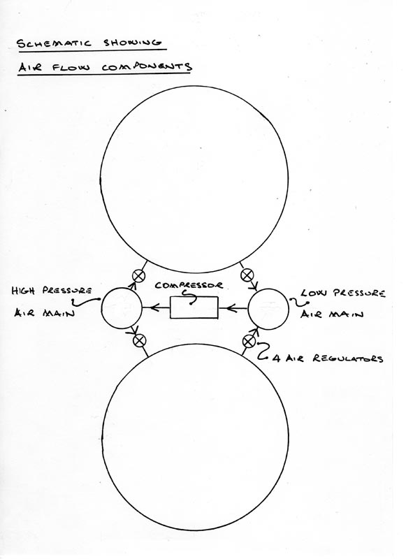
These two Air Mains are connected together at intervals by compressors, sucking air from the low pressure main and delivering it to the high pressure main. Connecting the Air Mains to the Tubes, again at appropriate locations, are regulators which control the supply of air behind and ahead of each pod and consequently the speed of the pod. At the start of the tube’s journey the pressure would also be produced initially by a compressor.
The schematic drawing shows the way all of the components are connected, except for the tube valves which are placed at intervals along the Tubes.
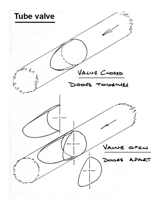
The tube valves consist of two symmetrical doors. Both hinge vertically and when in the open position swung apart into shaped recesses in the tube wall enabling the pod to pass smoothly between them. The valve design is such that if the doors have not swung into the recesses the pod will simply push them into place without any serious impact. With the doors closed together, seals along the contacting faces of the doors will help retain the air on the high pressure side and also help keep the doors shut.
The third drawing shows the sequence of tube valves opening and shutting, and the progress of pods through the Tube.
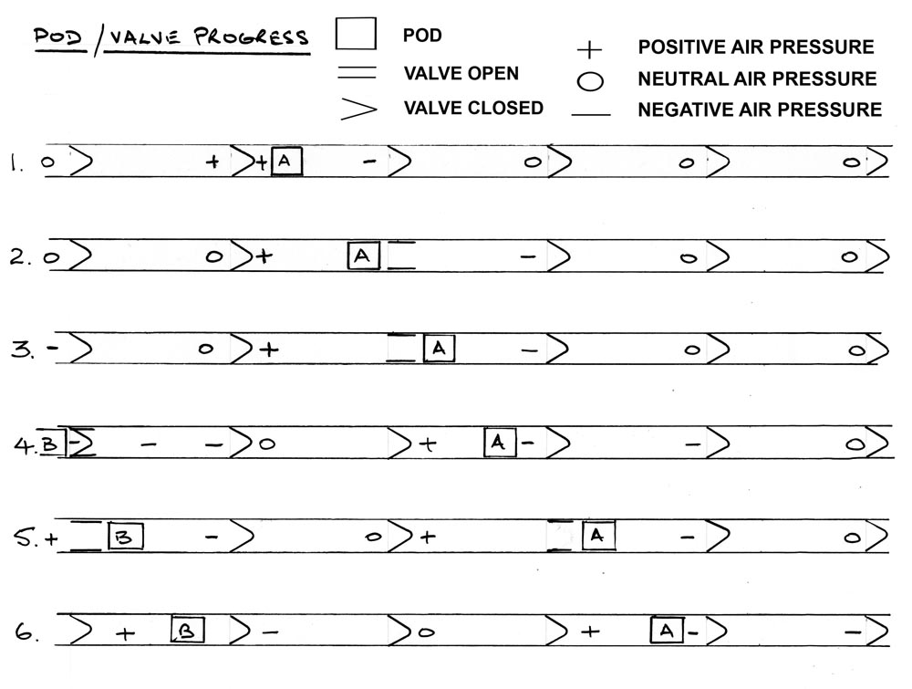
From rest, in the first tube section, high pressure is supplied behind the pod and low pressure in front. As it approaches the first valve this opens – where the pressure in the next section has just been reduced. After the pod has passed through the first valve, the valve closes and high pressure is supplied into the second tube section behind the pod. Air pressure in the first tube section, can now be reduced ahead of the second pod.
Various other factors such as materials to be used and the shape of some components are also important together with the tricky problem of junctions which all Tube Transport systems will have to resolve. I hope the announcement by Elon Musk of his ideas as Open Source may bring together more such ‘Men in Sheds’ musings from others and with collaboration the Tube Transport dream may eventually become a reality.
Text and drawings © Andy Marks 'A Man in A Shed'
Andy is also a partner in Skyscan a British aerial photography company.